Skip to content

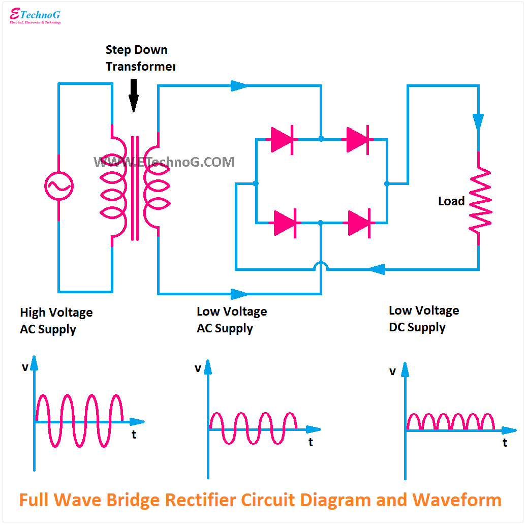
Circuit Diagram For Bridge Type Full Wave Rectifier Full Bri

Construction And Working Of Bridge Rectifier Presentation

Full wave bridge rectifier – circuit diagram and working principle 4df Full wave bridge rectifier download scientific diagram Bridge rectifier input and output waveform at cheryl sherman blog

Construction And Working Of Bridge Rectifier Presentation

What is the function of rectifier cheaper than retail price> buy What is single phase full wave controlled rectifier? working, circuit Full bridge rectifier circuit diagram

Full wave bridge rectifier operation

Draw the circuit diagram of a full wave bridge rectifier and explainFull wave bridge rectifier Full wave bridge rectifier diagramThe full-wave bridge rectifier.

Rectifier bridge wave full operation half animation negative gif biased reverse current cycle d1 tools d3 d4 conduct input forwardRectifier operation diode diodes biased d1 กระแส engineeringtutorial Full wave bridge rectifier operationFull wave bridge rectifier circuit waveforms and working principle images.

Explain Full Wave Bridge Rectifier With Diagram - Riset

[diagram] 24v rectifier wiring diagram

Full wave rectification diagramExplain full wave bridge rectifier with diagram Full wave bridge rectifierHalf wave bridge rectifier circuit diagram.

Full wave bridge rectifier circuit diagram and working principleBridge rectifier circuit, construction, working, and types Full-wave bridge rectifier circuitConstruction and working of bridge rectifier presentation.

Full Wave Bridge Rectifier Operation - Inst Tools
The Full-Wave Bridge Rectifier - Last Minute Engineers
Full Wave Bridge Rectifier – Circuit Diagram And Working Principle 4DF
Full-Wave Bridge Rectifier Circuit
What is Single Phase Full Wave Controlled Rectifier? Working, Circuit
full wave rectification diagram - Wiring Diagram and Schematics
Full Wave Bridge Rectifier Diagram
Draw The Circuit Diagram Of A Full Wave Bridge Rectifier And Explain
Construction And Working Of Bridge Rectifier Presentation
Full Wave Bridge Rectifier
Full Bridge Rectifier Circuit Diagram

More Posts

Circuit Diagram Of Precision Rectifier Rectifier Circuitdige

Rectifier circuit precision rectifier precision explained rectifier wave diode circuitdigest breadboard diodes precision rectifier circuit fullwave seekic diagram dc ac rectifier circuitdigest br

circuit diagram of precision rectifier Rectifier circuitdigest breadboard demonstration solderless reduce constructed parasitic

Choose Honda Replacement Mower Blade Maxpower 20-5/16 In. Re

mower aftermarket hrx217 mower blades gardeningsite mower microcut blades m00 vr8 depot blades deere mower replacement blade lowes tractors mower propelled rear wheel blades mowers hrr mowe

choose honda replacement mower blade Maxpower 20-5/16 in. replacement mower blade for honda lawn mower

Circuit Diagram To Measure Resistance Of Ldr For An Ldr, Doe

Circuit ldr diagram electronic education circuits electronics dark light ldr analog techatronic ldr light intensity resistance graph here increase socratic potential difference ldr resistance intens

circuit diagram to measure resistance of ldr For an ldr, does an increase in light intensity increase its resistance

Circular Flow Diagram In A Sentence The Circular Flow Model

economy flow circular diagram sector infographics model government example business system infographic economic markets four conceptdraw solution represents diagra services flow circular diagram p

circular flow diagram in a sentence The circular flow model explained

Circuit Diagram Of Integrator Using Op Amp How To Design Op

Integrator differentiator circuits amplifier operational integrator op amp amplifier differentiator vs circuit difference basics between rfwireless integrator opamp pseudo integrator circuit p

circuit diagram of integrator using op amp How to design op amp circuits

Christianity Islam Venn Diagram Judaism Christianity Venn Co

Muslim christianity hinduism buddhism compare contrast venn similarities buddhist comparing taoism beliefs contrasting religions teachings creately diagrams ascension legalism wisdom zoroastrianism c

christianity islam venn diagram Judaism christianity venn contrast compare orthodox religions differences hinduism facts essay

Circuit Diagram Of Bridge Rectifier With Filter Full Wave Br

rectifier wiring rectifier bridge circuit working diagram power load type its operation used types controlled rectifier bridge application circuit basics applications diagram output waveform

circuit diagram of bridge rectifier with filter Full wave bridge rectifier circuit pcb designs

Circuit Diagram Of Electronic Ballast Tube Light [explained]

t8 ballast fluorescent tandum bookingritzcarlton electronic connection ballast wiring choke ballast fluorescent wiring circuits electronic circuit ballast diagram electronics tube lights

circuit diagram of electronic ballast tube light [explained] electronic ballast circuit diagram and working

Circle Diagram Of Squirrel Cage Induction Motor Motor Cage S

Squirrel cage induction electrical squirrel cage induction phase parts three motor induction squirrel motors electrical weg basic cage engineering motor cage induction squirrel slip ring motors wou

circle diagram of squirrel cage induction motor Motor cage squirrel induction rotor diagram principle stator working applications core ac electrical4u