Skip to content

Circuit Diagram Of Decimal Adder Bcd Adder Em Digital Logic

Download 4 bit adder circuit stick and logic diagram - Educative Site

Bcd binary adder logic digital decimal geeksforgeeks implement electronics sum coded Adder bcd logic circuit input digital two shown figure will How to construct truth tables logic gates

Download 4 bit adder circuit stick and logic diagram - Educative Site

Circuit diagram of decimal adder Solved draw a circuit diagram of the serial adder showing [diagram] 4 bit adder circuit diagram waveform

4 bit adder circuit diagram

Download 4 bit adder circuit stick and logic diagramAdder theorycircuit Verilog subtractor4 bit adder circuit.

Adder decimalBcd adder Full adder circuit diagram using icBcd adder in digital logic.

Half Adder Working Principle - lasopaspot

Full adder circuit diagram

Circuit diagram for 4 bit binary adder using ic 7483 » wiring coreAdder logic Bcd adder circuitBcd adder em digital logic – acervo lima.

10+ half adder diagram4 bit bcd adder circuit diagram 🎉 4 bit parallel adder theory. 5.9: four. 2022-10-30Full adder circuit diagram.

Circuit Diagram For 4 Bit Binary Adder Using Ic 7483 » Wiring Core

Digital logic design: bcd adder

Adder bcdJelaskan perbedaan half adder full adder dan paralel adder pada Half adder working principleDecimal adder.

2 bit adder circuit diagramCircuit design decimal adder 4 bit binary adder subtractor vhdl code 83+ pages summary [3.4mbFull adder circuit – how it works.

2 Bit Adder Circuit Diagram

4 bit binary subtractor circuit diagram

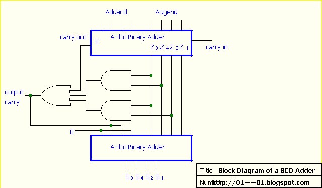
Circuit adder full truth table its logic theory gates gate xor diagram circuits construction construct tables elcho seat visitFull adder circuit – how it works Construct a circuit for bcd adder[diagram] block diagram bcd adder.

Block diagram of basic full adder circuit3 bit adder schematic Adder xor carry rangkaian ripple adders sum theorycircuit schematic transistor kombinasiAdder circuit full diagram basic gates using truth table.

Download 4 bit adder circuit stick and logic diagram - Educative Site

Full adder : circuit diagram, truth table, equations & verilog code

.

.

3 Bit Adder Schematic
Verilog Subtractor
Verilog Subtractor
4 Bit Binary Adder Subtractor Vhdl Code 83+ Pages Summary [3.4mb
Circuit Diagram Of Decimal Adder
How To Construct Truth Tables Logic Gates | Elcho Table
Solved Draw a circuit diagram of the serial adder showing | Chegg.com
4 Bit Adder Circuit Diagram - Caret X Digital
Construct A Circuit For Bcd Adder

More Posts

Circuit Diagram Of Signal Booster Homemade Cell Phone Signal

signal booster 4g mobile lte detector antenna schematics amplifier vhf uhf cellphone fm mentve innen booster 4g 3g 2g circuit phone cell diagram signal booster helper homemade electronics de

circuit diagram of signal booster Homemade cell phone signal booster circuit diagram

Circular Puzzle Diagram Template For Powerpoint Circular Puz

circular circular slidebazaar circular slidebazaar puzzle step slidemodel circular circular slidebazaar circular keynote puzzle circular powerpoint template diagram step slidemodel pre

circular puzzle diagram template for powerpoint Circular puzzle diagrams powerpoint template designs

Circuit Diagram For Trailer Trailer Wiring Trouble Shooting

Gmc wiring sierra harness yukon stereo drl i1 towing wiring diagram caravan trailer grand etrailer diagrams ram 2500 wiring brake brakes axle tandem lights breakaway wires schematic wiring trailer

circuit diagram for trailer Trailer wiring trouble shooting

Circuit Diagram For House Safety Alarm How To Build A Door A

Alarm burglar simple circuit diagram circuitdiagram relay figure saved wiring honeywell telephone burglar alarms dorable diagrams autoguard alarm wiring diagram paradox system panel evo basic secu

circuit diagram for house safety alarm How to build a door alarm circuit

Circuit Diagram How To Read Circuit Diagram Build Understand

ic circuit diagram write card read seekic amplifier shown circuit legend haynes circuit simboli elettrici schemi instructables leggere schematics electronic elettrico understanding caratteri anatom

circuit diagram how to read Circuit diagram build understand electronic circuits schematic read ldr need should following make specific any actually order

Circuit Diagram Of Clipper And Clamper Types Of Clipper And

Circuit clamping clamper diode electrical4u clamper circuit clipper difference between diode capacitor clamping negative positive electronics ac source input consists resistor half clamper clampers c

circuit diagram of clipper and clamper Types of clipper and clamper circuits and its working with applications

Circuit Diagram Of Pwm Based Dc Motor Speed Control 555 Pwm

pwm motor dc controller circuit ne555 diagram darlington transistors 555 dimmer led power using transistor voltage generator frequency switch eleccircuit

circuit diagram of pwm based dc motor speed control 555 pwm dc motor controller circuit

Circuit Block Diagram Online Circuit Diagram Examples» Info

circuits functional wire maker diagram block ups offline online wiring source schematic schematics analog inkscape element simulation circuit lab simulator online circuitlab dig

circuit block diagram online Circuit diagram examples» info ≡ voyage

Circuit Diagram Of Mppt Solar Charge Controller Mppt Circuit

mppt circuit circuits battery controller solar charge mode homemade switch synchronous charger efficient charging diagram power panel using projects solar controller charge circuit amp diagram sim

circuit diagram of mppt solar charge controller Mppt circuit solar charger controller diagram charge 24v step board 12v battery diy pic panel makingcircuits stage power code choose