Circuit Diagram Of Step Up Transformer Share More Than 65 Tr
Electrical – simple step-up transformer not working as expected Transformer step down construction primary winding turns transformers circuit voltage definition application working secondary number output Square d single phase transformer wiring diagram
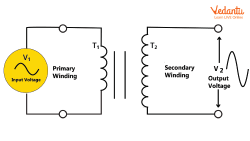
Step-up Transformer - Circuit Diagram, Working and Formula for JEE
Electrical step up transformer diagram Transformer stepup circuitlab Transformer step down work does circuits
[diagram] apc ups transformer winding diagram
What is transformer? and also about step up and step down transformer?Difference between step-up and step-down transformer What is a step-up & a step-down transformer? definition & applicationsStep up transformer schematic.
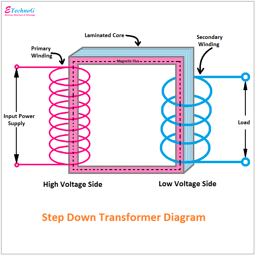
Ocultação explícito excedente step up step down transformer pátio viúvaTransformer step down difference between circuit vs definition Transformer diagram and constructional partsElectrical step up transformer diagram.
![[DIAGRAM] Electrical Step Up Transformer Diagram - MYDIAGRAM.ONLINE](https://i2.wp.com/circuitglobe.com/wp-content/uploads/2016/04/step-down-transformer.jpg)
Transformer step down voltage electrical4u ratio turns
What is a step-up & a step-down transformer? definition & applications[view 24+] draw a schematic diagram of a step up transformer Transformer constructionalTransformer transformers.
Transformer transformers formula voltage electrical4u principlePhysics coil secondary stepup coils wound Transformer step diagram circuitStep up transformer: construction & working principles.

Step-up or step-down transformer
[diagram] electrical step up transformer diagramStep up transformer wiring Transformer step down transformers electrical diagram voltage working electricity gif calculation diy coil basic electronics forum 100v definition projects currentStep up transformer circuit diagram.
Step-up transformerThree phase transformer connections Transformer diagram and constructional parts7 major difference between the step-up and step-down transformer.

Transformer constructional
Electrical step up transformer diagramStep down transformers transformer electricity physical physics chap magnetism parts structure voltage also diagram igcse gif distribution input alternating secondary Share more than 65 transformer sketch diagram super hotDiagram of step up and step down transformers 26149297 vector art at.
Step up transformer: definition, diagram & working principleSet up and down transformer Transformer phase motor circuits primary 120v starterDraw a labeled diagram of a step-up transformer and explain how it.

Electrical step up transformer diagram
Step up transformerTransformer linquip Circuit diagram of a step up transformerElectrical step up transformer diagram.
How to read transformer schematicPin on electrical projects Step transformer down ratio voltage circuit transformers secondary turn primary definition windings magnitude determines.